Global Cache – User Manual
iTach IP to Contact Closure Modules
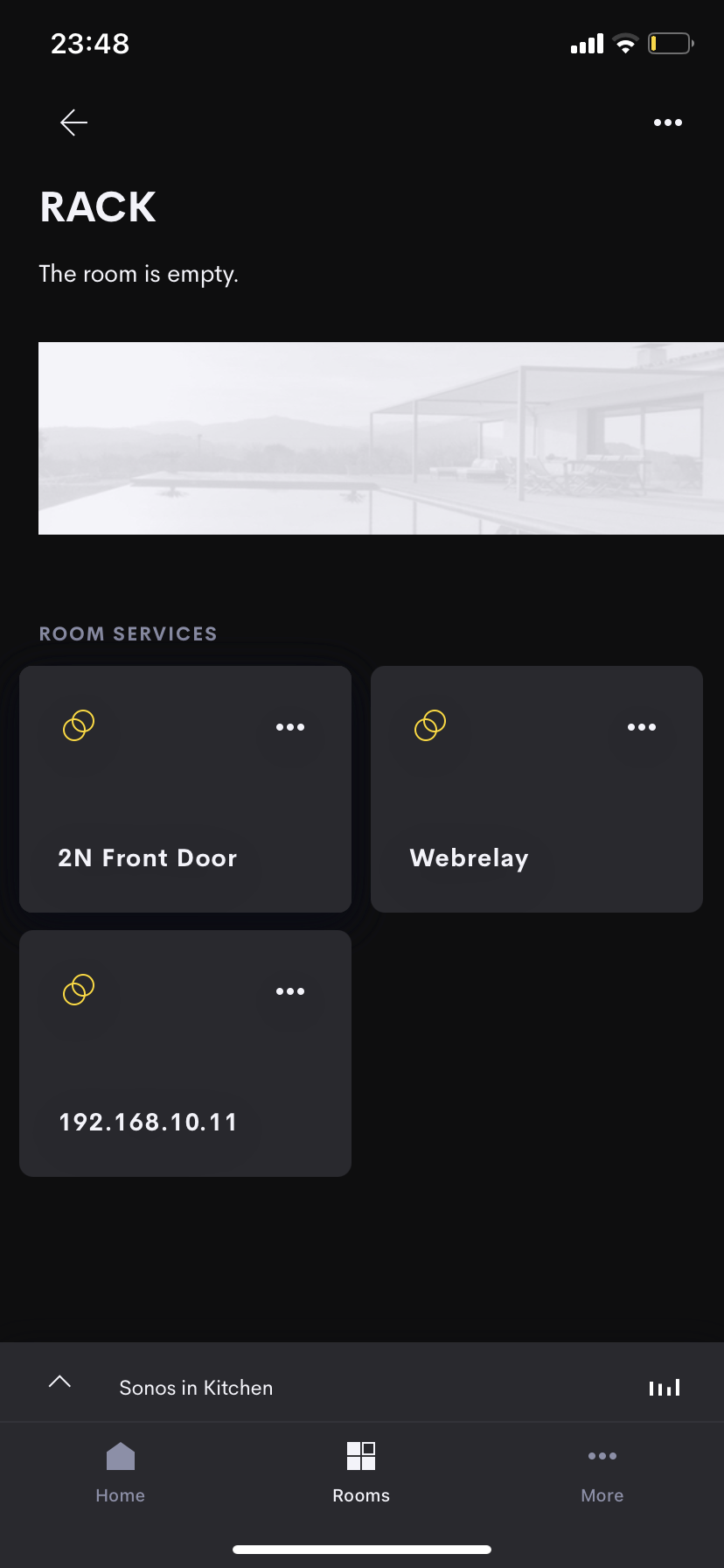
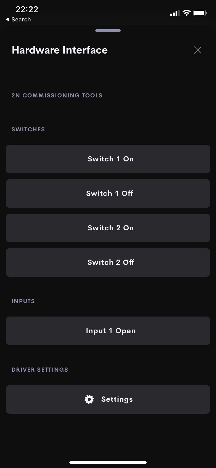
Crestron Home Setup
The information below details the specific configuration to allow the hardware to work with the associated Crestron Home Driver.
Our recommendations:
- Static IP address on the same Subnet
Global Cache IP to Contact Closure (IP2CC) Modules
Click here for the manufacturers Global Cache Configuration manual.
Hardware Covered
- IP2CC
- IP2CC-P
- WF2CC
IP / LAN Settings
If you have the WF2IR then please read here for specific setup info.
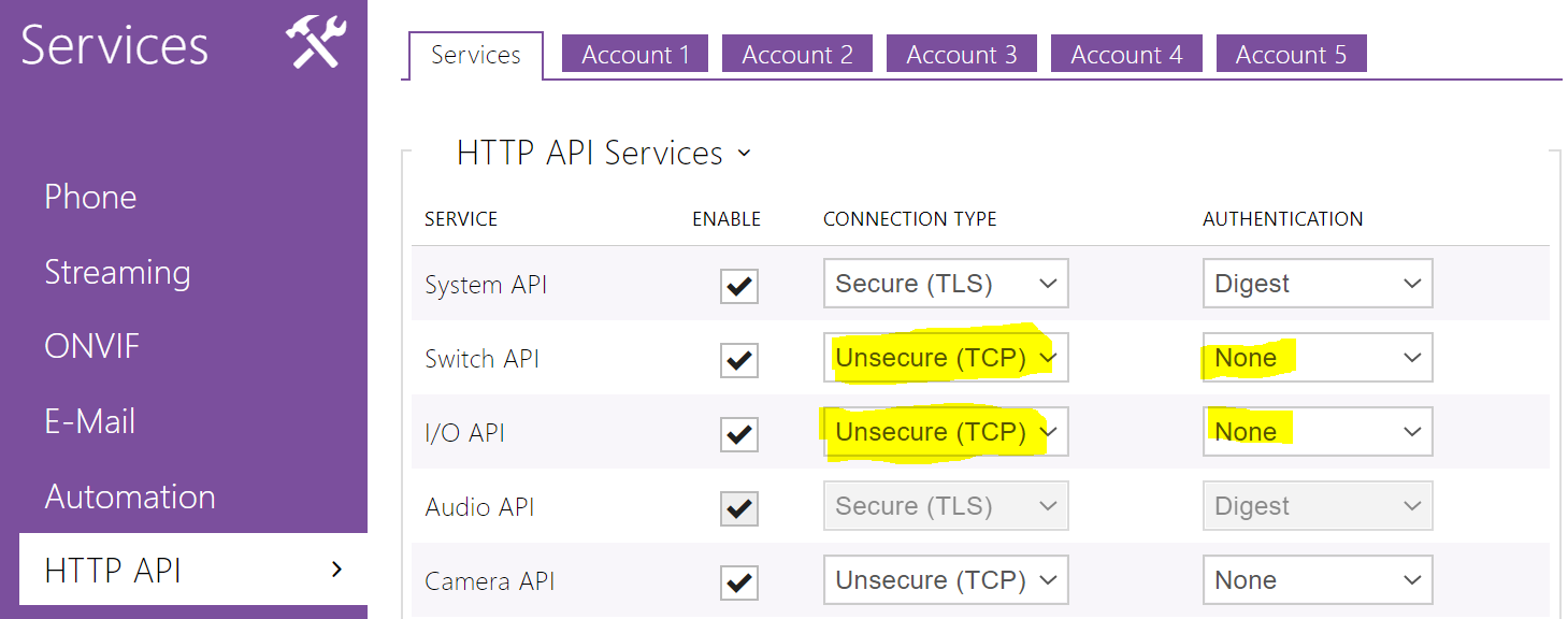
Global Caché network-connected products currently support network connectivity through Ethernet or WiFi, depending on product line and model. By default, all devices are configured to automatically acquire their IP configuration via DHCP. However, if a DHCP server is not available, devices will assume a default static IP address as specified in each device’s documentation. Configuration of a device’s network and I/O settings can be managed through the product’s configuration web pages, or via API commands if supported by the product Global Caché Unified TCP API (see here).
For detailed information about configuration and operation of the various products from a user perspective, please refer to each product’s Quick Start or User Guide here.
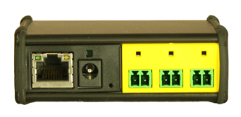
Connect both an RJ45 (Ethernet) network cable and power supply to your iTach unit. If the iTach is PoE (Power over Ethernet) enabled, connecting a power supply is not necessary.
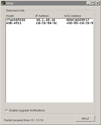
In its default configuration, the iTach TCP/IP models use DHCP to automatically obtain an IP address from your router. To determine the iTach’s IP address, download the iHelp application here.
Run iHelp on a Windows PC connected to your network. iHelp listens for Global Caché multicast beacons and displays the iTach IP address and other details within one minute. If a DHCP server is not present, defaulted iTach units will reside at IP 192.168.1.70.
Troubleshooting
iTach configuration can be reset to factory defaults by inserting a large metal paper clip into the small opening located to the right of the power connector. Only insert the paper clip approximately 1/8” (3mm) in. The LEDs on the front of the iTach will rapidly blink in unison, indicating a reset. Use a light touch when resetting your iTach, as force may damage your iTach hardware irreparably.
Network Port Usage
| Service | Port / Protocol | Detail |
| Control | 4998 (TCP) | Control Port |
| Discovery Service | 9131 (UDP) | The beacon is a UDP packet sent to the multicast IP address 239.255.250.250 on UDP port number 9131. Any system listening to this address and port will receive the periodic beacon message. The message is sent 3 seconds after power on and then at random intervals of 10 to 60 seconds thereafter. |
| Web Server | 80 | The port used to display the control and configuration web pages |
Network Capacity: Notes on Simultaneous TCP Connections
The iTach Series of devices supports 8 simultaneous open TCP software connections.
Firmware
The Global Cache Firmware is accessible through Global Cache support portal here.