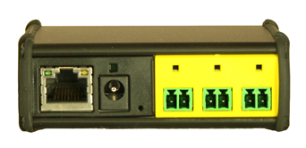
The information below details the specific configuration to allow the hardware to work with the associated Crestron Home Driver.
Our recommendations:
Static IP address on the same Subnet
Global Cache IP to Contact Closure (IP2CC) Modules
Click here for the manufacturers Global Cache Configuration manual.
Hardware Covered
IP2CC
IP2CC-P
WF2CC
IP / LAN Settings
If you have the WF2IR then please read here for specific setup info.
Global Caché network-connected products currently support network connectivity through Ethernet or WiFi, depending on product line and model. By default, all devices are configured to automatically acquire their IP configuration via DHCP. However, if a DHCP server is not available, devices will assume a default static IP address as specified in each device’s documentation. Configuration of a device’s network and I/O settings can be managed through the product’s configuration web pages, or via API commands if supported by the product Global Caché Unified TCP API (see here).
For detailed information about configuration and operation of the various products from a user perspective, please refer to each product’s Quick Start or User Guide here.
Connect both an RJ45 (Ethernet) network cable and power supply to your iTach unit. If the iTach is PoE (Power over Ethernet) enabled, connecting a power supply is not necessary.
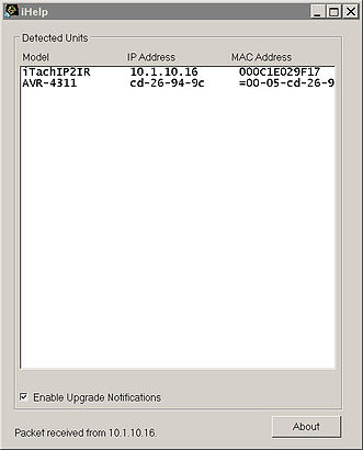
In its default configuration, the iTach TCP/IP models use DHCP to automatically obtain an IP address from your router. To determine the iTach’s IP address, download the iHelp application here.
Run iHelp on a Windows PC connected to your network. iHelp listens for Global Caché multicast beacons and displays the iTach IP address and other details within one minute. If a DHCP server is not present, defaulted iTach units will reside at IP 192.168.1.70.
Troubleshooting
iTach configuration can be reset to factory defaults by inserting a large metal paper clip into the small opening located to the right of the power connector. Only insert the paper clip approximately 1/8” (3mm) in. The LEDs on the front of the iTach will rapidly blink in unison, indicating a reset. Use a light touch when resetting your iTach, as force may damage your iTach hardware irreparably.
Network Port Usage
Service
Port / Protocol
Detail
Control
4998 (TCP)
Control Port
Discovery Service
9131 (UDP)
The beacon is a UDP packet sent to the multicast IP address 239.255.250.250 on UDP port number 9131. Any system listening to this address and port will receive the periodic beacon message. The message is sent 3 seconds after power on and then at random intervals of 10 to 60 seconds thereafter.
Web Server
80
The port used to display the control and configuration web pages
Network Capacity: Notes on Simultaneous TCP Connections The iTach Series of devices supports 8 simultaneous open TCP software connections.
Firmware
The Global Cache Firmware is accessible through Global Cache support portal here.

2N Gate IO Crestron Home Driver
A Driver for Crestron Home allowing control of the Mode Lighting Edin+ system.
DIN-UBC-01-05-PLUS – Universal Ballast Control Module
DIN-PSU-24V-PLUS – Power Supply Module
DIN-02-08-PLUS – 8 Channel Dimmer Module
DIN-DBM-32-08-PLUS – DALI Broadcast Module
DIN-INT-00-08-PLUS – Input-Output Module
DIN-MBUS-SPL-04-PLUS – 4 Port M-BUS Splitter Module
System Architecture
SEE detail below for configuration of IP and Gateway Control
Express Setup:
Important – 5 Golden Rules – Network Processor Unit (NPU)
If you don’t read anything else… If you don’t generally read manuals then we ask that you just read these 5 golden rules:
In the configuration editor: scenes are defined in columns, inputs are shown in rows. The intersection between the two is where the input triggers the output.
Channels should always be named as follows: : . The colon : symbol must be included
The configuration-editor username is always “configuration”. The password is whatever you set it to be.
An I/O module which has some channels set as an input, and some set as an output will appear twice: once in the outputs section, and once in the inputs section.
Your NPU must have it’s own unique IP address, and be on the same sub-net as the computer which you are using to browse its’ web-pages.
IP / LAN Settings
All aspects of the eDIN networking can be configured through the web interface.
The IP address of the NPU must be unique on the LAN. If you want to access the NPU from outside your LAN, perhaps from another computer on the Internet, then you’ll need to know the site’s public IP address, and you’ll need to set up Port Forwarding on your router.
You can select which ports are used for each of the network services offered by the eDIN NPU. Each service has a default port, which you do not have to change if you do not need to:
BY DEFAULT, OUR DRIVER USES PORT 26 in the ‘Enable gateway control’ section (see image below), this can be changed if required
The Embeded WebServer eDIN is configured using a web browser. No eDIN-specific software or tools are required.
To access the embedded web server, contained within the eDIN Network Processor Unit, connect the NPU and your computer to a LAN (Local Area Network).
Alternatively the IP address can be set manually. This is only recommended for networks that do not have a DHCP server, as otherwise the DHCP server may allocate the IP address that has already been manually set for the eDIN module to another device. That would then mean that there are two devices with the same IP address on the same network, which will cause problems.
Once you know the IP address of the eDIN NPU, type it into the URL bar of your web browser.
eDIN is compatible with many web browsers that run Javascript, JQuery and AJAX, these include: Microsoft Internet Explorer v7 onwards Mozilla Firefox v3 onwards Opera v9 onwards Safari v4 onwards Google Chrome v2 onwards
Network port usage
Service
Port / Protocol
Detail
Gateway Control
26 (TCP)
Mode Lighting Crestron Home Driver – MUST use port 26 by default (can be changed if required)
Remote Control
22 (TCP)
Control of scenes via “telnet” using the standard commands: SCENEnnnnGO (where nnnn is the scene number)
Discovery Service
19182 (UDP)
Enables a PC to automatically discover the eDIN NPU on the LAN.
Diagnostic Consol
23
Used for system analysis
File Server
21
For uploading and downloading the configuration, scripts, webserver pages and style-sheets etc.
Web Server
80
The port used to display the control and configuration web pages
NTP
The clock can be set automatically by connecting to an internetbased time server. Your site’s network administrator will need to ensure that the port specified has permission to connect to the NTP server specified. The Refresh Delay is the number of seconds between each synchronisation.
Network Capacity: Notes on Simultaneous TCP Connections The eDIN NPU supports 8 simultaneous open TCP software connections. Typically a web-browser connection will use up to four of the simultaneous open connections to achieve faster page-loading. However the connection times will be brief, so connections will be freed automatically when they are not in use. Therefore in practice you can have more than two users using the web-browser at one time. A device that is remote controlling the eDIN system, for example an AV system processor (e.g. a Crestron unit), will use one connection at a time. Therefore in a typical set-up you can have one web browser and four remote-control devices simultaneously maintaining open connections to the eDIN NPU.
Setting Areas and Scenes
The Configuration menu in the Web interface will take you to the page where you can set the Areas and Scenes.
Configuring eDIN The eDIN processor may be configured in the following areas, in the following order: 1. Select modules, and set up hardware 2. Create and edit scenes (output actions) 3. Create and edit triggers (input actions) 4. Create users, and assign access privileges 5. Configure network settings and security
Setting Up Modules, Scenes and Triggers The configuration screen is used to setup the hardware modules and what they do. There is a quick setup feature that can do much of the work for you automatically. From the front screen select Configuration to access a page which shows a spreadsheet-type view, with the modules in a column on the left, and scenes in columns on the right.
Configured with a Global/All area with all devices available for main ON/OFF switching (top left)
All other have other areas setup with at least 5 scenes per area
Firmware:
How to Update the Software Inside eDIN
From the front page click on Settings and then select the Software Upgrade tab.
The current version of firmware and the editor software are shown. If you ever need to contact Mode Technical Support, please make a note of these. To update either part click here to access the Firmware Update page. eDIN contains two sets of software: 1) The firmware, which handles M-Bus communications, memory management and all of the internal features that make up eDIN. 2) The Configuration Editor, which is the embedded web application, visible to engineers and users via the web browser. The firmware has been written and created by Mode Lighting (UK) Ltd and can not be modified externally. However updates are available from time to time, which contain new or enhanced features as part of our programme of continual product development, based on customer feedback. The Configuration Editor, or web-application, has also been created by Mode Lighting (UK) Ltd. Using various web-technologies such as CSS and Javascript it is possible for a suitably skilled developer to modify the look and feel of the web pages, including the Style-Sheets and all graphics associated with them. For more information on this, please contact the sales department to discuss OEM options and Web Customisation. You can make a backup of the current firmware/webapplication using the Backup links, or upgrade the eDIN NPU, using the Upgrade options.
The Mode Driver Series allows sophisticated control of the Mode Edin+ Lighting System. Along with standard lighting functionality there is the now the ability to adjust scenes and tuning.
Features:
Configuration options allow for scene adjustment and tuning.
Dali, Mains dim and switched Circuits supported.
Site wide license allows you to integrate the whole home.
The 2N Driver Series allows sophisticated control of the 2N Intercom systems. Along with standard intercom functionality between the intercom panel and the gate/door control there is now the ability to lock/unlock, detect states of lock/unlock and set AutoLock functionality.
In addition to control from the Tile and UI this driver has Sequencing actions that can be used via a quick action that can be selected from the actions button when a SIP Call is received from the front gate station.
Door Lock Function:
We control Lock/Unlock state of the door lock.
Implementation:
We control either Switch 1 or Switch 2 in the 2N Relay. This is configurable in the admin setup along with the IP address of the 2N device.
The Driver calls on the 2N rest API to activate the Switch on the unit.
On the unit the Switch must be configured to control the desired output device.
Door sense functionality updates the status of the tile feedback when the door is opened without the lock being released by an action from the driver. It will also indicate if the door is opened when the lock is enabled. See Feedback states above.
We use cookies on our website to give you the most relevant experience by remembering your preferences and repeat visits. By clicking “Accept”, you consent to the use of ALL the cookies.
This website uses cookies to improve your experience while you navigate through the website. Out of these, the cookies that are categorized as necessary are stored on your browser as they are essential for the working of basic functionalities of the website. We also use third-party cookies that help us analyze and understand how you use this website. These cookies will be stored in your browser only with your consent. You also have the option to opt-out of these cookies. But opting out of some of these cookies may affect your browsing experience.
Necessary cookies are absolutely essential for the website to function properly. This category only includes cookies that ensures basic functionalities and security features of the website. These cookies do not store any personal information.
Any cookies that may not be particularly necessary for the website to function and is used specifically to collect user personal data via analytics, ads, other embedded contents are termed as non-necessary cookies. It is mandatory to procure user consent prior to running these cookies on your website.