2N DoorStation – User Manual Intercoms Access Unit

Updated for V3 Features Scroll down to see!
User manual for the 2N hardware interface module.
- Allows you to control your 2N Doorstation directly from Crestron Home
- Relay and IO both exposed in Crestron home
- Supports the Crestron Actions & Events
- Compatible with any native controls or connect to one of our tile drivers.
This hardware interface is intended to simplify the connection of your Crestron Home system to the popular 2N range of doorstation hardware.
The Switch controls and IO input can be used in tandem with the SIP call functionality to allow a complete solution. In addition we offer a range of Door and Lock UI Tiles which can be used to give a user interface to the hardware.
NB: the UI Tile and pages associated with this tile are not intended to be “customer facing”
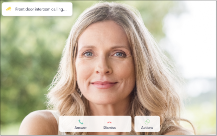
When a 2N Intercom is used in a crestron System for Calling the user is presented with a Call page as seen below.
Supported Devices
This driver supports the API on the following devices 2N IP intercoms, 2N® SIP Audio Converter, 2N Access Unit 1.0, 2.0, M
2N Licence Requirements
Licensing on 2N has changed and for most of the functionality of our driver you now dont need any additional license.
The only additional license available is the Gold Licence and you will still need this if you want to use the motion detection parts of our driver.
Read more about this change to licensing from our Friends at Aldous Systems !
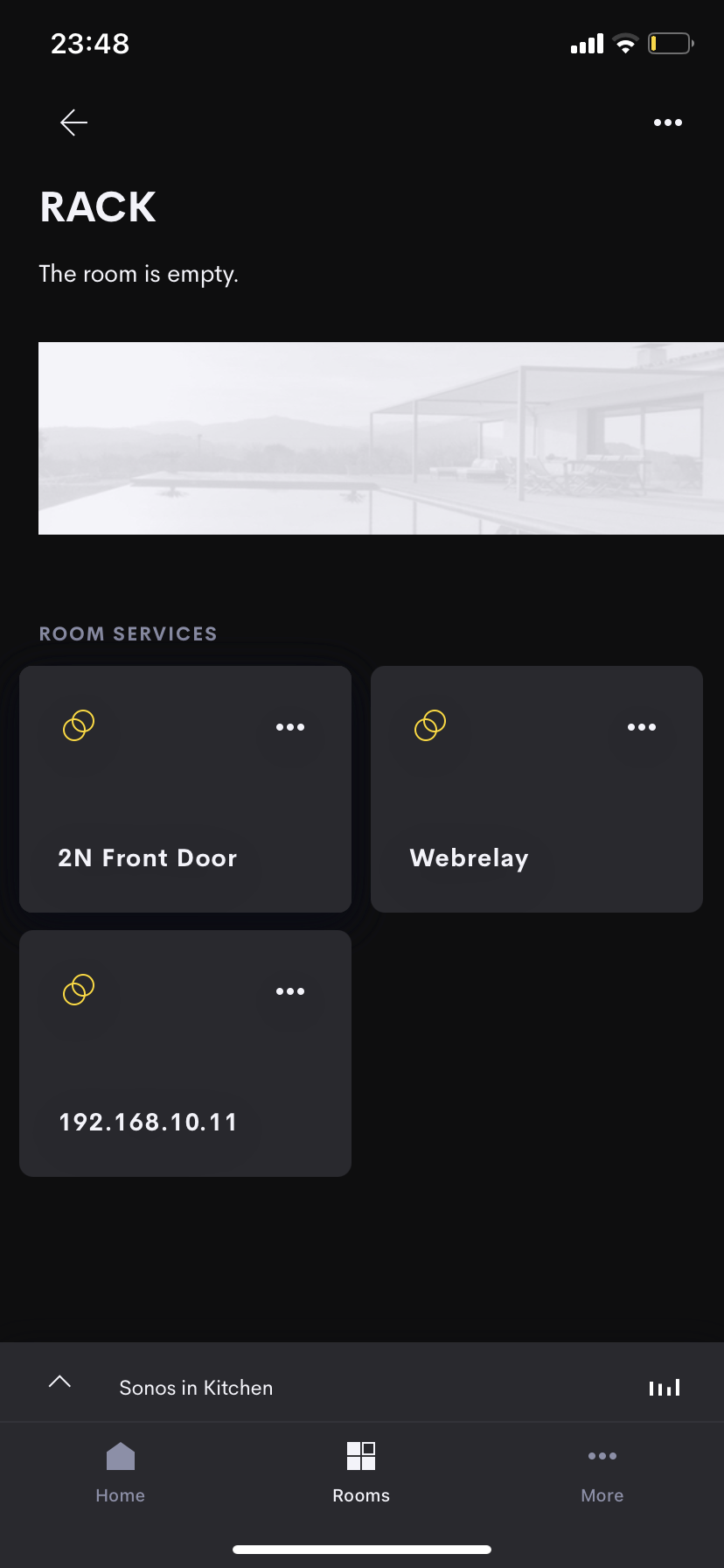
Rack Room Tile
This Hardware interface driver provides a simple UI intended for use by the integrator to verify the operation of the hardware.
The driver would generally not be client facing and would loaded to a “hidden” room in the system such as a rack room.
All hardware interface have a generic image showing two adjacent rings.
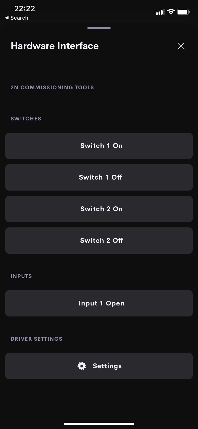
Main Page Actions
The home page tile navigates you straight to the main user interface of the driver.
This pages allows you to test the function of the controls and see monitoring of the IO via the Crestron Home App.
Actions and Events
Actions
| Action | Description | Notes |
|---|---|---|
| Switch 1 On | Activates Switch 1 | |
| Switch 1 Off | Deactivates Switch 1 | |
| Switch 2 On | Activates Switch 2 | This can be used to end all an incoming call when the open gate button is pressed. |
| Switch 2 Off | Deactivates Switch 2 | |
| Switch 3 on | activates Switch 3 | |
| Switch 3 off | deactivates Switch 3 | |
| Switch 4 on | activates Switch 4 | |
| Switch 4 off | deactivates Switch 4 | |
| Dial Panels | Makes a call from the 2N Intercom to the rava:CRESTRON call group. | |
| End Dial Panels | Ends the call make using the "Dial Panels " command. | |
| End All Sip Calls | Ends all active calls on the 2N Intercom device | Supported from v4.2.0.0 |
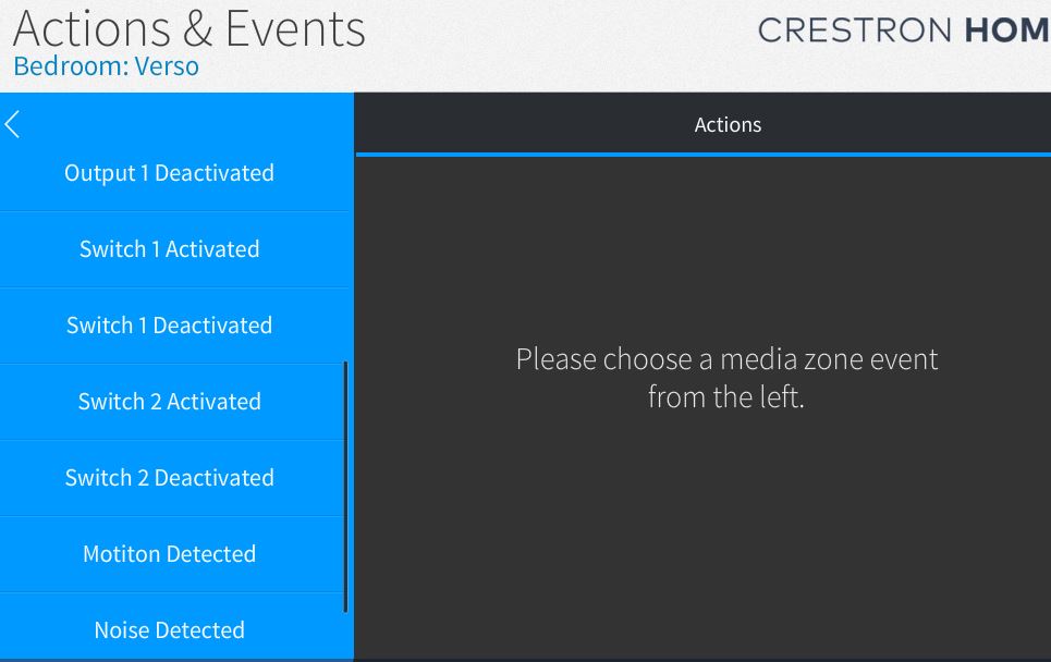
Events
| Event | Description | Notes |
|---|---|---|
| Input 1 Closed | Event called when Input 1 closed | |
| Input 1 Opened | Event called when Input 1 closed | |
| Input 2 closed | Event called when Input 2 open | |
| Input 2 opened | Event called when Input 2 closed | |
| Input 3 closed | Event called when Input 2 opened | |
| Input 3 opened | Event called when Input 3 closed | |
| Input 4 closed | Event called when Input 4 opened | |
| Input 4 opened | Event called when Input 4 closed | |
| Relay 1 Activated | Event called when Relay 1 activated | |
| Relay 1 Deactivated | Event called when Relay 1 Deactivated | |
| Output 1 Activated | Event called when Output 1 activated | |
| Output 1 Deactivated | Event called when Output 1 Deactivated | |
| Switch 1 Activated | Event called when Switch 1 activated | |
| Switch 1 Deactivated | Event called when Switch 1 Deactivated | |
| Switch 2 Activated | Event called when Switch 2 activated | |
| Switch 2 Deactivated | Event called when Switch 2 Deactivated | |
| Switch 3 activated | Event called when Switch 3 activated | |
| Switch 3 deactivated | Event called when Switch 3 deactivated | |
| Switch 4 activated | Event called when Switch 4 activated | |
| Switch 4 deactivated | Event called when Switch 4 deactivated | |
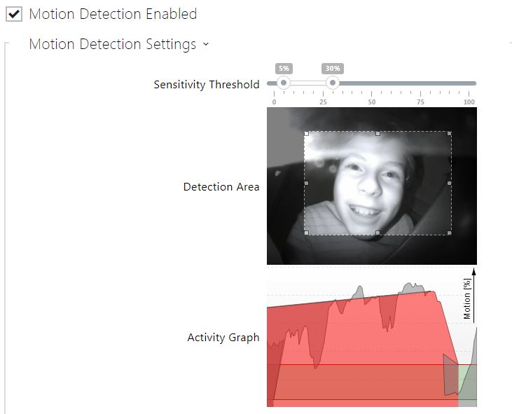
| Motiton Detected | Motion Detected based on video detection area and sensitivity threshold setting. | |
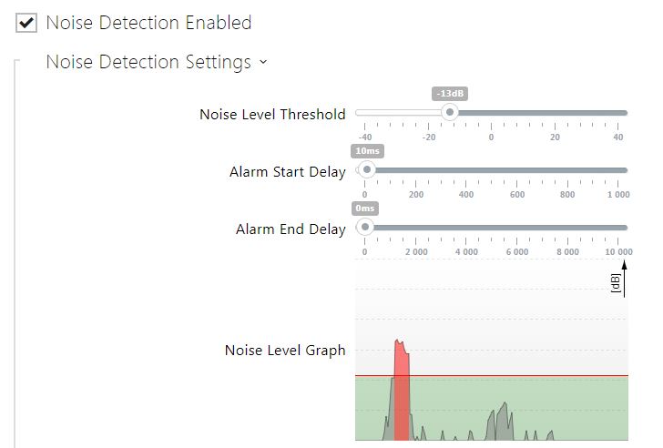
| Noise Detected | Noise Detected based on noise detection level threshold. | |
| Call Button Pressed | Call button on intercom presses ( Commonly used to trigger a doorbell using our Sonos Chime driver) |
SIP Call Flow ( This functionality is not dependent on the driver)
We include and explanation here as the setup and usage is very common when using 2N in Crestron home.
When a guest or visitor presses the call button in a crestron home system configured for a 2N intercom the Crestron Rava Panels in the system ring with the incoming call from the intercom. This is done by setting up the dialer in the intercom
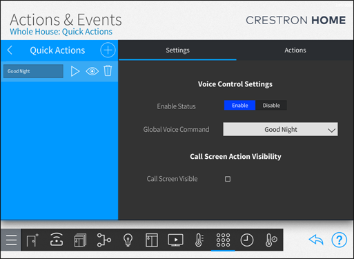
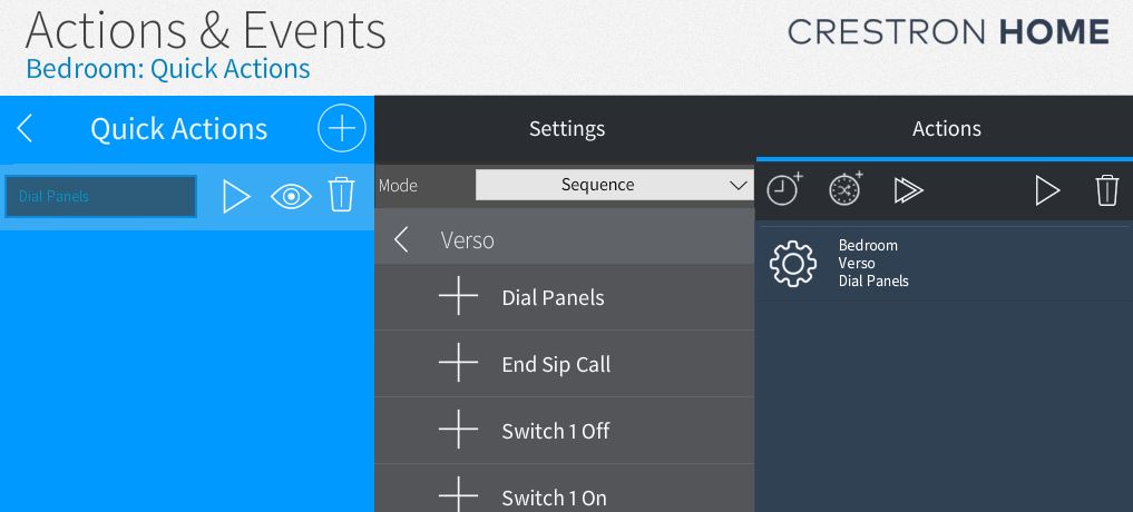
When the Crestron Home user presses the Actions button on this page a subsequent page showing all whole house quick actions is shown.
A common setup is to make a “whole house quick action” which opens the Gate using the 2N Switch Action
See more on setting up the call flow here
For the Quick Action to appear on the Call Screen you must tick the checkbox in the Settings Section of the call Action
More info here
2N Device Setup and Connection
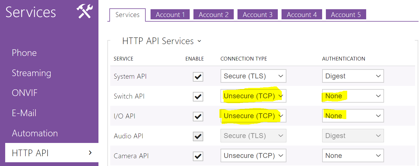
To make use of the Switch and I/O API you dont need any additional license on the 2N.
We suggest when first connection you set authentication to None.
The Driver requires a TCP Connection Type and can support Digest , Basic or no Authentication.
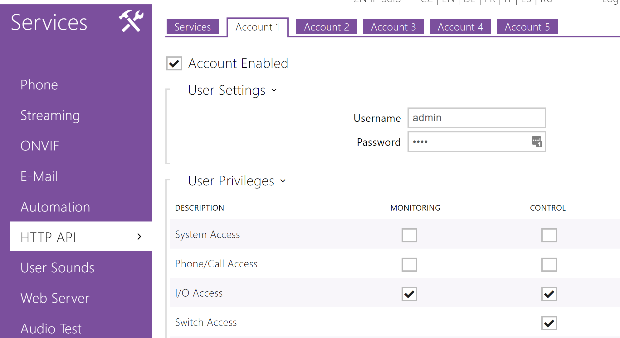
If Authentication is used a user must be created and given control and monitoring on I/O Access and control privileges on Switch Access .
You need to create a user and give that user the privileges:
NB: the user is not the same as the user that you use to get into the web Interface.You have to add and enable one of the accounts on the HTTP API Page.
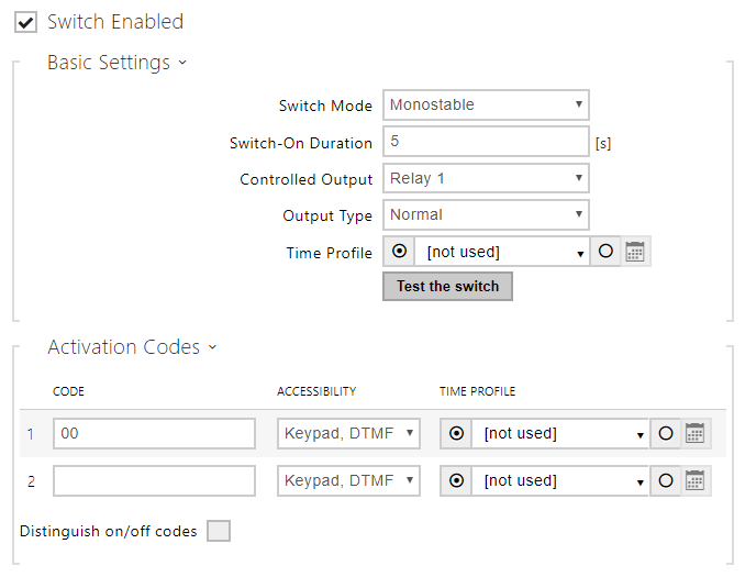
The function applied to Switch 1 or Switch 2 are configured in the 2N web interface.
2N Doorstation Setup Video
New Features v3
Summary
In the version 3 upgrade to our drivers we added a number of features to the standard 2N Module.
We exposed the State of the Relay in addition to the State of the “Switches”. This means if these are controlled by other systems you can keep everything in state.
We also added a couple of new monitored items to the events list.
With the Audio Licence on your 2N Intercom you can enable noise detection. Motion Detection is enabled on the internal intercom camera with the Video Licence. To read more about what licenses allow what on 2n follow this link.
In the version 3 module these events are brought into Crestron home as an Events. See a deomstration on our youtube channel here
Call Control
This new function allows basic control of the SIP calling on the 2N Intercom. When the call button is pressed on a 2N intercom setup for crestron home the intercom Dials “rava:CRESTRON” which initiates a call to all touchscreens in this default ring group.
NOTE: CRESTRON is the default ring groups for all shipping TSW‑x60 / 70 touch screens. This driver only supports this standard default CRESTRON call group.
Actions
(In addition to previously supported features)
- Dial Panels ( Calls the Rava Dial Group CRESTRON)
- End SIP Call Ends the call made by the Dial Panels Action ( Will not end a cll made from the call button)
Events
(In addition to previously supported features)
- Switch Actions ( Activated / Deactivated)
- Relay
- Motion Detected
New Features V4.2
Now Supports :
- Switch Functionality to Switch 3 and Switch 4 both Actions and Events *
- IO Events for Inputs 2 – 4 *
where the hardware supports these.
-
 2N Simpl Windows Module£100.00
 -
 2N Doorstation£0.00 – £182.50
 -
 Global Cache IP2CC£60.00
Some More From 2N