Ethernet to DMX control via Crestron

I am currently working on a module for control of a Ethernet DMX Node from a Creston Control system.

With the DMX standard being used more and more in architectural lighting a solid Ethernet DMX Node and integration module is a must for many projects!

Microphonics™ – Thats not a word!

Microphonics™ isn’t a word is it?  It is now!

Microphonics

Microphonics

As those of you who know me will be aware I am a big fan of Automation. The use of sensors in control systems is the clever and progressive way forward.

Putting light switches when they are not the best solution is a waste of money, time and energy. However specifiers and installers are still scared of occupancy sensors.

They are scared of the call-out when Mr Client has been plunged into darkness while reading his paper in “The Library”.

This has been a real problem and often the only way to counter the problem is to up the time delay off to a sufficient level that we are confident that a traditional good quality PIR occupancy will re-trigger the time delay off.

This of course is not an ideal solution as we end up having lights and fans on burning energy for longer than we should have.

Some companies looked at gate sensors systems by which a control system could monitor a person entering and leaving a space and combine these with a PIR to get a more accurate result. These systems have a number of limitations including the problems cause by multiple users and high cost due to the requirement for multiple sensors.

Sensor Switch have produced a dual technology sensor which combines a PIR detector with a high gain microphone and some clever audio processing to achieve a good result.

Motion is first detected by  the PIR and the the microphone is switched on to listen for continued occupancy.

The system filters out repetitive noises such as plumbing and HVAC sounds to allow the sensor just to trigger from sudden noise changes such as created by a user.

I will be very interested to find out how well the unit deals with background music!

sensorswitch1

DMX Architecture Were here to help!

DMX as a standard was developed for the entertainment industry and has been adopted for use in large architectural projects over the last few years.

Lot of articles on the internet cover the electronic details of what DMX is which is of interest to those wishing to create products that send or receive and wish to comply to the standard. This is of no interest to lighting designers and electrical contractors. The architecture of a DMX control system is governed by the other side of the standard EIA485 this describes the electrical system that DMX uses as it’s bedrock. This is the roadway that the communication runs on; if this underlying infrastructure is not correct then the communications trying to use it will falter and the system will never be stable and reliable.

DMX Standard was originally adopted for use by “lampys” at touring events where large entertainment systems are setup up for a show or a series of shows before being all packed up into a number of trucks and moved to the next show.

Power distribution for these shows is all done using flexible rubber cable and Ceeform cables connecting different parts of the systems using portable distribution units. The construction industry has a more cost effective and longer lasting method using steel wire armour and fixed distribution boards around a project.

The distribution for a project is designed in a drawing office by an electrical engineer.

Power Distribution Drawing

The engineer designs the system by  completing calculations and specifying suitable cabling and distribution panels to ensure that the system will work correctly and safely.

DMX is used by the construction industry primarily to control colour change lighting. By it’s nature a single colour change unit uses three or four channels of DMX and puts a unit load on the DMX controller of the system.

In the same way as the electrical distribution example above DMX requires design. It’s a simple thing to say but frequently the architecture of a DMX system is left to chance. When a ring main is required in a electrical system often the exact numbers of outlets and types of outlets will not be specified or indeed if a small change is required then the installing electrician will make the design change in a flash. This is simple as a the architecture (limits on length, number of outlets, spurs) is well known by that electrician through years of installing these simple systems.

DMX is a simple architecture however colour change systems can use a large number of DMX recievers and control channels. In addition to this systems should be designed to allow section testing by isolation and also to ensure downtime in certain areas of the system will not affect control over other parts of the system.

Simple DMX systems have a single cable connecting a number of fittings allowing a controller to control attributes on all these fittings independently. In reality all but the most basic DMX systems require boosters, splitters and termination to allow a stable system to exist and to ensure minimum installation time.

DMX is a not a proprietary control standard it is used by countless manufacturers and the size and complexity of DMX control required in a project is on the increase all the time.

So don’t chance it ! Were here to help!


More Reading:

The DMX 512-A Handbook


Save energy with Lighting control systems

Energy saving light bulbs have taken over the world in the last couple of years so much so that later this year (2009) the major retailers in the UK plan to remove filament light bulbs from there shelves.

However in most projects with lighting controls low energy light bulbs are not to be found. In fact most systems do not support them.

Dimmable energy saving light bulbs are still in the early days of development and are not yet as cost effective as their non-dimmable predecessors.

Lighting control systems can however give significant energy savings.

  • Control empowers correct usage of multiple fittings. With more circuits to control only the lighting that you need for a task need be turned on saving 100% on lighting that is not required.
  • Off during non-activity: Using timed off’s and proximity sensors in a lighting control system we can ensures that lights are not left on when the need not be.
  • Daylight harvesting: Daylight harvesting allows lights to be automatically dimmed to a level dependant on the amount of natural light reaching the target area. This saves in energy usage as the quantity of additional lighting used is limited to what is required exactly.
  • Dimming at full power: Not running lamps at 100% can result in massive extension of lamp life.

Contact us to discuss how you can implement energy saving in your next project.

Mode Lighting and the 17th edition

The recent introduction of the 17th edition regulations means a number of changes in the protection of circuits.

Mode Lighting units such as the tiger and Evolution have no main isolator and hence even in the previous edition of the regulations a mechanical isolator was required to isolate the incoming power to the unit to carry out mechanical and electronic maintenance.


The best solution seems to be three independent RCBo’s mounted in an external housing local to the Evolution control pack.
1 RCBO for each phase/bank of breakers – this requires that the pack neutrals are split for each RCBO and that the pack power supply (3 phase + neutral connection) is rewired to the mains supply side of the RCBOs. A warning label should be applied to the pack to this effect.
If a single phase supply is used for Evo/Tiger, it becomes easier, in that assuming RCBOs are only needed for one or two of the banks of breakers, the PSU can be powered from the remaining bank (ie all 3 PSU live inputs can be connected to the bottom of one set of breakers).
In all cases, it is essential that the load live and neutral outputs are connected to the relevant set of outputs, otherwise the resultant imbalance will cause tripping.
If you need advice on design or installation of a lighting control system please contact us and we can look over your project and ensure it meets all the current standards.

RS232 handshaking for the non-technical user

A recent project meant i had to explain a RS232 integration to non technical users.

RS232 is a very simple way of communicating between two systems.

You can think of it as a simple speech communication a good example being the exchanges of speech that go on in a parliment or any sort of debate.

Members of parliment wish to speak to the house but if they all speak together then the message will be lost or confused due to the inability to hear the different messages coming from each parlimentarian.

To solve this problem RS232 has hardware flow control or handshaking.

When each member of the house has a message they stand and raise there hand to say that they are ready to speak. The speaker of the house then indicates to one member that the house is ready to hear their message and in this way one message at a time is heard.

In an RS232 system only one line of communication is established. Imagine a secretary and her boss dicatating a letter but the secretary has no short hand skills. Each small section of the letter dicatated by the boss is brought to an eand by the Secretarty saying “STOP” while she finishes writing that section on the word processor. When the secretary is ready to continue she indicates this to the boss and the next section .

In the RS232 system these “STOP” and “GO” messages are indicated by the high or low level of the CTS flag. The sending system has a similar flag (RTS) which indicates that it has data ready to send to the recipient.

9 Pin Connector on a DTE device (PC connection)
Male RS232 DB9
Pin Number Direction of signal:
1 Carrier Detect (CD) (from DCE) Incoming signal from a modem
2 Received Data (RD) Incoming Data from a DCE
3 Transmitted Data (TD) Outgoing Data to a DCE
4 Data Terminal Ready (DTR) Outgoing handshaking signal
5 Signal Ground Common reference voltage
6 Data Set Ready (DSR) Incoming handshaking signal
7 Request To Send (RTS) Outgoing flow control signal
8 Clear To Send (CTS) Incoming flow control signal
9 Ring Indicator (RI) (from DCE) Incoming signal from a modem

Manual Control of Automation

Automation is great and sales people sell lighting control systems based on the ability to automate tasks.

But as anyone who sets a daily alarm knows automation is not great when the alarm wakes you up on a Saturday morning instead of allowing you your well deserved lie in!

This is a very simple example of how automation requires a really well thought out quality specification. When setting the alarm the simple choice is to tick the “every day of the week” !

When doing lighting controls a basic automation requirement is that lights turn off automatically after all staff have left the premisis. This ensures that if lights are left on they will not stay on all night which saves on lamps and energy costs.

However on special occasions for example the christmas party the premisis is to be used after closing to host the party or on a special corporate launch night you invite your major client to a reception to lanuch your latest new product.

The presentation is then cut abruptly short as the lights dim to zero. At best this causes inconvinience and at worst can present a real health and safety problem as people are literaly left in the dark.

I remember an example of this would happen each year at our local church. The exterior of the building is floodlit by the local council controlled from a timer control located in a panel outside the church. Each Christmas the midnight service to bring in Christmas day would take place at 10:30pm and church-goers would be able to find there way around the church from the light of the floodlights. However on Christmas morning the lights would turn off at 12:30 am meaning that we would exit the church to darkness!

The simple solution has been provided in HVAC systems for many years. A three position switch on a panel allow selection of “OFF” , “ON” and “AUTO”. This allows the system to be forced off , forced on and forced to do whatever it is supposed to do depending on any automation that has been programmed into the system.

This is a really simple local overide that works and should be used as a starting point for local overide.

However our automatic specification was written to stop somebody leaving the lights on overnight. This local overide gives them exaclty this power again so we have failed to meet the specification.

Another heating control analogy is the “+1h” button or “Next Step” button often found on simple heating controllers this enables the users to slightly atler the auto mation by telling the system that for the next hour it is one hour ahead of the real time (allowing you to turn on or off the heating early) or to tell the system that for the rest iof this period of automation you want the system to do the functionality of the next period of automation.

This is better as the period of non-automation is restricted if you like the automation is automatically switched back on!

There are many methods of solving this problem and unfortunately often the problem is solved by removing the automation due to the fear of an un suspected turn off.

With good design features of lighting controls systems can be fully utilised and not hindered.

1-10v Lighting Control Installations whats the standard?

1-10V

A recent project highlighted the common mistakes made when  wiring   1-10v DC analogue control.

When wiring for DMX or Dali there is a widely accepted standard which can be followed but with 1-10v control there is no such standard I guess the thought is always but it’s so simple how can it go wrong!

The Basics:

Electronic ballasts display a 10V DC between there 0V and + control inputs. When this connection is open circuit the ballast provides full brightness on its connected lamps.

A controller sinks current to reduce this control voltage to 1V to achieve maximum dimming (lowest brightness).

The Simple Test:

Short the + and 0V connected to one or a number of ballasts in parallel and ensure that the connected lamps dim to the lowest dimming level. On removing the connection the lamps should return to 100% brightness.

A more advanced tests:

Ballast / group of ballast test:

Using a DC ammeter the current required to reduce the control voltage can be checked. The current is noted in the specification for all ballasts and is generally less than 1mA. If a ballast is producing a higher current then it may be faulty.

Controller Test:

To check, connect the controller, set to lowest brightness and measure the voltage on the control line. The value

should be 1 V or less.

These golden rules should be followed by specifiers and installers to ensure the best operation of these types of systems:

1-10v Golden Rules:

  1. Study product data sheets, installation instructions, and specification guides and/or handbooks carefully before designing and applying one of the various control systems.
  2. Check carefully the needs, wishes and expectations of the customers and users with the possibilities of the preferred or applied control system.
  3. Ensure that sufficient knowledge of the control system is available on the side of the contractor. Education possibilities should be available.
  4. Mark cabling at beginning and end. Use the correct cabling within the maximum lengths.
  5. The control line is isolated from the power line but not at safety extra-low

    voltage (SELV). Cables and terminals that are approved for 230 V must

    therefore be used.

  6. Avoid humidity and temperature shocks for the electronic components during installation.
  7. Connect dimlines according polarity: plus to plus and minus to minus.7)   Treat dimline wiring like mains voltage wiring.
  8. Check that the working of the lighting installation is 100 per cent correct before connecting or commissioning the control system. It is advised to let the installation run for 24 hours before commissioning. We recommend that you allow new lamps to burn in for at least 50 hours at 100% luminous flux.

  9. Be careful during the insulation tests  (when using mega ohmmeter).
  10. Carefully check the wiring and connections of the control part before starting with the configuration / commissioning.
  11. Make proper earth connections for the metal optics.
  12. The routing of cabling should ensure that neither the mains power supply cable nor the control cable runs parallel to the output cables from the ballast as these operate at high frequency and may cause interference.
  13. See manufacturers specifications for cable type but our recommendation is a minimum cross section of 0.5mm2

Lighting Control System Standards

Aims

This short document aims to present the common Lighting Control System Standards used in the lighting industry today and give a short explanation of their development, uses, advantages and disadvantages.

Introduction:

Lighting can be switched on or of and it can be dimmed that is the light output of the lighting source varied to different levels in between off (no light ) and full on ( the maximum light output of the source)

Electrical Dimming

When halogen lighting is in use the dimming is simple and can be carried out either remotely or locally. A dimmer of this type (for a halogen load) achieves the dimming by reducing or increasing the level of the r.m.s. voltage and hence the average power.

Traditional Triac or thyristor dimmers use switching techniques to achieve this varying voltage. Inductors are the other main component of the dimming circuit and these are used to suppress interference caused by the switching. When a dimmer is at 50% they are switching the greatest voltage and the interference in the circuit is at its maximum. This is the cause of the vibration in the inductors that causes a buzz to be heard near to the dimming units. The inductors add weight to the dimmers and the suppression provided is often not sufficient to prevent the buzzing being heard on audio systems that share a closely related power supply.

Although the most simple form of dimming this type of dimming is not without it’s problems:

Low voltage lighting is now in very frequent use in projects using a wirewound or electronic transformer to provide a 12 v voltage for the lamps.

Traditional wirewound transformers provide an inductive load to the dimmer and the current of the load lags behind the voltage. Once triggered a triac requires the flow of current to the load through the device to maintain its operation. When the current falls below this threshold the device will switch off. If the current lag from an inductive load is sufficient the current flow in the circuit will not reach a sufficient level to maintain the triac and the device will turn off givingflashing and unwanted effects.

To avoid this effect the length of firing pulse on the dimmer can be varied to last long enough for the current to ‘catch up’ .

When using electronic dimmers only dimmers designed for use with a dimmer should be used although others may work they will not work for long.

Electronic Dimming

Electronic ballasts

Fluorescent and High intensity discharge lamps are frequently used in both residential and commercial projects. These use electronic ballasts to provide the supply to the lamp or lamps. Electronic ballasts usually change the frequency of the power from the standard mains (e.g., 50 Hz in uk) frequency to 20,000 Hz or higher, substantially eliminating the stroboscopic effect of flicker (100 or 120 Hz, twice the line frequency) associated with fluorescent lighting (see photosensitive epilepsy). These devices are often based on SMPS topology and allow dimming via pulse width modulation.

Generally these ballasts will be permanently connected to a mains power supply and also have one set of control connections either two or three core dependant on the type of control.

LED Electronic controllers

Led lighting is more and more popular due to the energy efficiency and the colour change possibilities without the need for filters.

LED units are however more complicated to dim than halogens. Dimming using a traditional dimmer above at best will not work and at worst will cause damage to your control gear and your dimmer.

Electronic controller specifically designed for controlling LED’s exists in both single channel devices and most commonly in three or four channel devices to accommodate colour change.

These devices provide a constant current supply to the LED and vary this supply using pulse width modulation to lower the duty cycle of the led and create a dimming effect.

These devices come in many shapes and sizes depending on what you wish to control. They also come as either integral units with LED power supplies or stand alone units which are connected in conjunction with and LED power supply.

Control either local or remote and if remote using 0-10V DC, DMXgenerally.

Cold Cathode Electronic controllers

The term Cold cathode is usually used to describe concealed lighting in coffers of cornices and is often used as an indirect up lighter. The name is in fact a description of the technology (fluorescent lighting for example is known as hot cathode). Cold cathode tubes are usually divided into two groups, those filled with Neon (red) gas and those filled with Argon (blue gas). The range of colours available is created by the use of different phosphors on the inside of the tubes which react with the ionized gases and emit the particular colour light.

Lighting Control System Standards –

0-10v DC (also described as analogue)

The most basic of these control signals is 0-10V DC (the same as is used as the basis of most Triac dimming systems!) However small electronic ballasts are always located locally to the fitting and hence the DC control pair must travel from the processor to the fitting and may be susceptible to interference.

Pros

·Simple to wire and understand

·Simple to test with simple test equipment

Cons

·Most common fault is inverted +/- wiring

·Susceptible to noise

DSI – Digital Serial Interface

DSI is a digital protocol for controlling lighting in permanent installations. The standard uses uses a single byte to communicate the lighting level ( 0-255 or 0x00-0xFF).

In a DSI system each lantern or group of lanterns has it’s own control cable running from the processor or controller. There is no addressing of lanterns to be set.

Pros

·Simple to wire .

·Relatively simple to test with relatively simple test equipment

Cons

·Large systems have many control pairs running back to central system

·Initially a proprietary standard exclusive to Tridonic

DMX-512 –Digital Multiplex

DMX is a well know control protocol based on RS485 standard. The standard was developed for use in the entertainment industry to control multiway dimmers and intelligent lighting. Until recently the standard was never used in construction applications however due to the advent of RGB LED and cold cathode systems requiring more detailed control DMX has become the protocol of choice in these situations.

A DMX512 controller is connected to fixtures or devices in a multi-drop bus topology commonly called a “daisy chain”. 512 fixture attributes can be controlled on each DMX universe and if control of more is required additional universes can be added.

A fixture attribute may be a single channel of a dimmer.

Or a single colour on an RGB LED controller.

Fixtures are addressed using a menu structure or DIL switches. If a device has multiple fixture attributes such as a 12 channel dimmer, a 3 channel LED driver or a 32 channel intelligent light then the address of the channels first fixture will be set and the following channels will follow in sequence.

e.g. a 3 channel LED driver with starting address 1 will use

ØChannel 1 Red

ØChannel 2 Green

ØChannel 3 Blue

Channel 4 and onwards are “free” to use for other fittings.

Many devices utilize automatic addressing and while this has it’s place for certain applications I must say that from experience I am not a fan.

Pros

·Strict adherence to the daisy chain topology must be followed (no Y-splits).

·Allows very accurate control.

·Long distances are possible even without buffers.

·

Cons

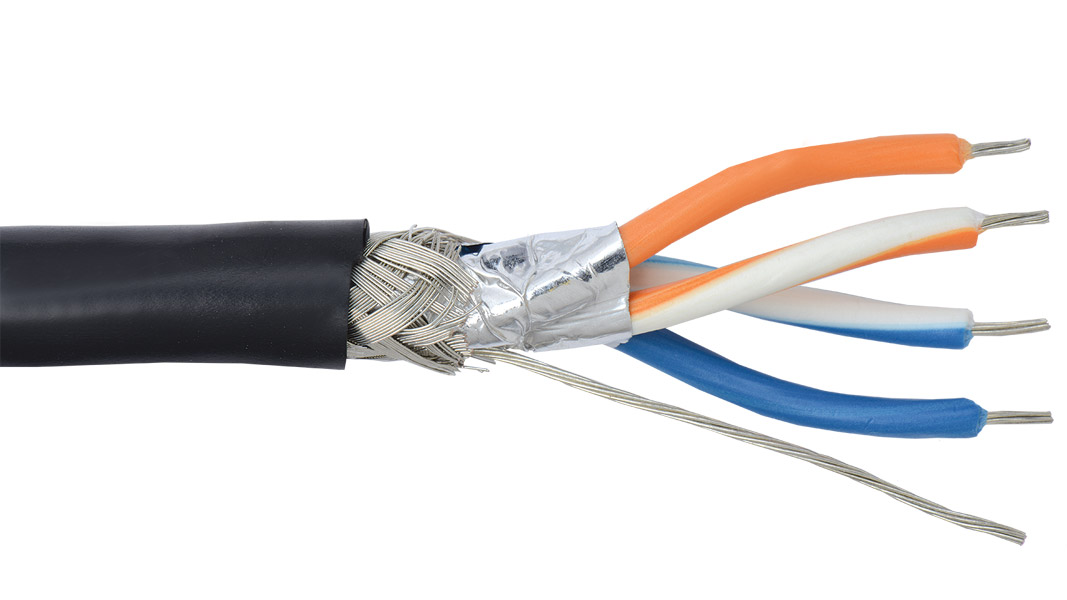
·Specific shielded cable must be used CAT 5/6 is not suitable.

·Difficult to fault find at signal level

DALI – Digital addressable Lighting Interface

DALI is and open standard protocol introduced as a rival to DSI and a successor to 0-10V control systems which still dominate the industry. The protocol allows control over a number of fittings using bi-directional data exchange over single bus with a maximum of 64 devices.

Devices are addressed individually and in addition to allowing control over the device feedback is provided to the system giving status of the device.

DALI has group and scene commands as part of the protocol allowing the reduction of data traffic and reduced network latency.

Pros

·Simple to wire – It requires only a pair of wire to form the bus connecting all devices on a single DALI network.

·Relatively simple to carry out basic tests with relatively simple test equipment

·No topology restrictions STAR and T’s are OK!

Cons

·The limiting factor of 64 addresses is not enough for large installations.

·Difficult and expensive to test and fault find

·Speed of the system (1200 bits per second ) can mean visible delay in larger installations

Copyright Neil Silver Lighting Control 2007

Neil Silver is the Technical Director of Lighting Control. He carries out a wide range of design and programming work in both commercial and domestic lighting controls systems.

Lighting controls and design

I visit many high end developments programming lighting controls. When we are just contracted to do the programming we arrive on site after all the first fixing has been completed and sometimes even later than that at a very late stage when the project is near to completion.

You can understand control panels for a lighting control system being placed in the traditional spot near the entry exit point of the room. I don’t think this is the future of lighting control and comes from the old technology of electric light switches but that is fordifferent rant!

On many of these sites I find Audio Visual control panels in the same place at the entry exit point of the room.

When I was 16 I bought myself a simple Sony Midi System ( CD , Tuner ,Cassette ) with a simple remote control. This allowed me my first glimpse into luxury control!!

From the comfort of my bed or from my easy chair or indeed from my computer desk I could quickly and simply control my music for the room from each location. Not rocket science I hear you say but really effective simple control.

Move forward fifteen years and you would think that the intervening years would have moved us forward especially with a large budget on a multi-room penthouse project.

However even with a well known control system and a huge budget the control in the bedrooms of theses projects have arguably a less flexible and overall a lower overall standard of control than my bedroom did fifteen years ago.

Why ?

Who does the design of these projects ?

(I often find myself asking mostly under my breath). There are generally three different answers; The Salesperson of the control system told us to put them next to the light switches, The Electrician or developer who had no drawings had to make the decision and went with what they know, The Lighting Designer or architect who spent hours of quality work on the fixture placement and selection and did the controls as an after thought.

Am I being a bit harsh on all these individuals?

The Salesperson should not be doing the design of the lighting or of the controls. For one thing if a salesperson designs anything they will always design with a bias to their products which may not be the best solution. Design is an involved process that requires interaction with other design professionals involved who a sales person generally does not have access to.

The Electrician who does not have a drawing goes back to what they know. Electricians are trained in electrical system design. This design is design of systems to comply with the wiring regulations and the training does not extend to anything but simple positioning of items for ease of use. If I am being really harsh the level of training for lighting given to most electricians is limited to two-way switching with a number of sparks struggling with an intermediate. In fairness as well a building site with deadlines and other contractors is no place to be making cool calculated design decisions.

Lastly there is our Architect or Lighting designer who as I said has spent hours of time making a really great (hopefully) lighting design for the project. On a number of occasions that’s where they stop. The Drawings are produced with no thought to lighting controls and design whatsoever. On many occasions the design is produced with no thought to maximum loadings of control gear which is really unforgivable but I would say that not thought to lighting control is equally wrong. In this article today I’m only talking about the relatively simple design decision of placement of controls not even looking at the next stage of what these controls do and how they interact with other control in different positions. The limit for most designers is to write a multi-scene scene setting for a system in the form of a table giving circuit numbers and relative intensities. On the placement of the controls the designers all seem to have been to the same training as the electricians and cannot bring themselves to look out of the box and try and make the design better. Architects and designers talk about movement of users through a design as a very important concept in the design process. In the modern automated house the movement of individuals is dictated by control of the lighting and audio visual systems within the space and should hence get a healthy proportion of attention from professionals with suitable understanding in controls at the design stage.

Lighting controls can serve many purposes. In a commercial project they can ensure that the designers vision is maintained night after night, year after year hence realising the value of the design work maintaining the “look” In this application the placement of controls is usually quite simple but I still see horrific examples of getting it wrong. In Domestic properties the placement of controls is much more complicated. Modern designs involve open plan areas with many entry and exit points within large open spaces. The solution given is often to throw loads of controllers at these points and have them all providing the same functionality.

Neil Silver is the Technical Director of Lighting Control

He is an Electrical and Electronic Engineer with many years experience in controls, Audio Visual and Lighting Systems

Select currency
GBP Pound sterling