The Design Black Hole

In the AV industry consultants, designers and integrators have always struggled with defining the functionality of systems.

I’m not talking about the process of gathering the requirement here but of documenting it.

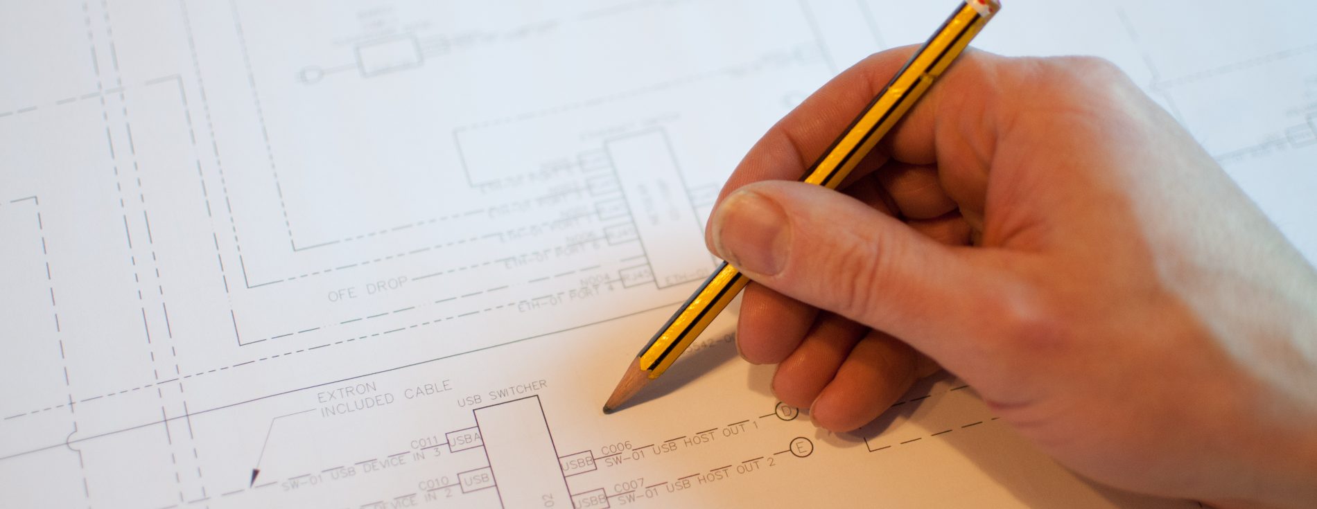
We produce, mostly, great schematics which define the boundaries of the possible based on the hardware. The idea of these drawings containing black boxes which are highly configurable is not new.

Black boxes, by my definition, differ from other hardware items on a system drawing as although they may have a static number of input and output ports their core functionality is open to a high level of configuration.

A display has, potentially, a few functions. It’s a video switcher, a display, an amplifier with onboard speakers, it even has some control features including auto switching of the video switch and volume control of the amplified sound level.

Take for example a display with a single connected HDMI and RS232.

Display Schematic

It’s reasonable to glean from a schematic alone that the functionality of this piece of hardware in this system is to display a video stream of the connected source and that power and input control will be using the RS232 port.

Contrast this with a control processor pre-Ethernet.

A control system processor does stuff.

Take a simple system with a two-button keypad and a display.

A Schematic showing a control system a content player and a display accurately describes the system. On functionality we can make some assumptions but without some additional information they are just that.

It is possible that:
Button 1 turns system on and Button 2 turns system off.

However, it is also possible that:
System turns on and off based on an internal timeclock and Button 1 raises volume and button 2 lowers volume.

To discover the actual requirement we need a functional scope which has hopefully been produced by some good needs analysis that informed the system design.

Control systems in the form of processors and touch panels with IO allowing control over 3rd party devices have been around since the 80’s and the discussion over how to specify their operation has produced little in the way of standards.

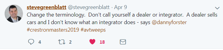
Infocomm, pre Avixa did some good work on this but this is not widely adopted across the industry. Crestron’s CAIP scheme and subsequently CSP (Crestron service providers) has, at its core, the requirement for programmers to produce a functional specification but even this is not standardised across the body of CSP’s.

DSP’s are common place in mid to large systems. Again these are of course by our definition black boxes.

But like traditional non Ethernet connected control systems DSP’s pre Dante and Digital had fixed number of inputs and outputs. Even post Digital standard such as OBAM proprietary hardware such as IO extenders also included on the schematic would ultimately define the inputs and outputs of the system.

The Functionality of the processing going on in that DSP must be defined just like a control system. The language of this definition is often tied in with the control system which provides control IO to this audio processing however audio processing has a language of it’s own. These boxes provide room and system specific equalisation, gain structure, Acoustic Echo Cancelling along with VOIP functionality.

Often the DSP tools are graphical in their nature providing a schematic like trail which defines that dynamic functionality of the DSP. In our system functionality specifications we define all interactions between control system and the audio processor.

The new world  “Not just black boxes but hidden lines.

Dante Spoken Here

Although the change has been coming over the years for me the, “Dante Spoken Here”, sign at the ISE Show in 2018 all over the show were the sign that Audio over IP was now wide spread.

Now Schematics don’t just contain black boxes but hidden lines! The traditional skill of tracing a signal path through a schematic from input to output becomes a whole new skill.

A single LAN connection to a device can be obfuscating control, video and audio in that single cable and potentially multiple routes to disparate locations.

One approach to this by engineers is to view the IO potential in a traditional way and connect it all up like a patch panel. I have found systems where all 64 Dante channels are connected from DSP to Audio Desk for “future use” but for me this misses the point.

It’s the same misunderstanding as coding an object oriented code in a single file monolith.

In the world of Dante in addition to the Schematic which shows the physical connections between devices documentation showing the network routes must be created intelligently based on the functional requirements of the system.

These routes need to be well named for system maintainability and usability.

Having Multiple Dante 1, Dante 2 ,Dante 3 around a system dont mean anything. These should have a Name or Numbering convention just like cables.         

These concepts of defining the routes apply to other types of audio over digital such as USB IO.

Dante I/O How many In’s and Out’s?

Add to this video over IP in whatever flavour is being used or in some cases a mix of different types.

Listing video encoders and video decoders on a drawing doesn’t tell you what routing possibilities you might need to setup. Some devices in the market can be configured to be Decoders and Encoders but the Fixed IO on the device doesn’t always inform you on this without some further information.

Are devices to be matrixed or is the system designed as a one to many DA?

Are you using audio breakaway on the encoders / decoders?

And in a final twist some of these products also in addition to all of the above speak Dante so need to be included in your Dante routes.

These challenges are real for us in our day to day business where provided with schematics for a project we need to suck out the functional intent from the pre-sales design engineers and the project engineers.

We often work with the designers explaining to them the additional documentation we need to produce to clarify to the programmers and commissioning engineers what they need to implement.

  • Virtual Matrix Drawings
  • VLAN Network Design Drawings
  • Dante Routing Naming Schedules
  • GUI Functional Requirements
  • Automation Functional Requirements
  • Audio System Functional Requirements

If you need help with filling in the gaps reach out to us to help!

Image Credit : Julian Böck

Design Assist

I’m really looking forward to Crestron Masters in Madrid next week. The very fact that this event now has a Keynote speaker reflects the change in this event over the years I have attended.

At my first masters there was no Keynote speaker but a Crestron Staffer filled the space very well, masters were altogether smaller affairs in those days.

I followed on twitter from afar Masters 2019 in the US and picked up that Danny Forster and Architect and TV personality was chosen as the 2019 Keynote. I guess for guys in the UK Danny is the equivalent of a mix of Richard Rogers and Kevin McCloud.

I don’t know if we have a seperate keynote speaker next week in Madrid ( will update later!) or if we will be seeing Danny’s full keynote.

I had a glimpse of some of his key points but have not heard the full keynote.

Two items stuck with me which I think are really interesting. The first is what audio visual companies call themselves. The term in Integrator has become the go to title for the industry with the term Dealer.

Leading audio visual companies in the UK all use this terminology although I find myself having to regularly explain “What is an Integrator” to end users and design professionals.

I have always found the term dealer to be very accurate for some smaller companies as it sometimes it accurately describes the process of selling boxes without understanding the aspect of integration which is key to our industry. I think it is for this very reason that companies moved to the word Integrator i guess meaning an organisation who has expertise in integrating audio visual equipment. Before Dealers we had a lot of companies with Consultants in their business name or description Consultants in the industry! These business like my own usually offered a chargeable design service as part of their business model but more often than not any design work was an internal process supporting the Sales or delivery of projects.

Of Course we still have consultants in the Industry but the term has changed to describe companies who provide consultancy as their sole or primary service. Many IT and building service consultancies have opened dedicated AV departments and of course some dedicated Audio visual consultants exist within the industry.

I wonder what the marketing guys will come up with next in the year that has seen Infocomm become Avixa.

Maybe we will all become storytellers , or experience engineers!

I think that with the convergence of IT , Collaboration and AV we need to get better at explaining what we do!

The other thing that I found interesting in was the mention of Design Assist. Both in the Lighting Industry and in the Audio visual industry it’s a conversation I have had with many other design professionals throughout the years. The conversations about needing help far outnumber the number of times that we are engaged at an early stage to assist with design.

The video posted via the CI website talks around the early involvement of integrators in the design process.

I offer design as one of my four core services, as an engineer I sell professional services to others in the Audio Visual and Electrical Services industries. My clients are mainly integrators but we do have some relationships with end users and with design professionals who engage us to provide technical expertise to a project.

I have seen over the years so many times the problem when a company brings it’s sales focus early into the design stage of a project. Conversations become about boxes rather than function. Early designs become fixed in architecture meaning only one solution will fit when th project goes to tender later.

It seems to me CSP’s are very well placed to serve Danny’s need for design assist or sometimes know as early contractor involvement.

However if architects or indeed consultants in the industry don’t have this expertise in-house then they need to engage contractually with the experts they need, there is no such thing as a free lunch and free design funded by the promise of future sales or manufacturer tie in is worth little to the process.

Design assist is based on the premise that engaging the delivery team in the design process will have an overall benefit on the whole project. Coming back to the first section around what an integrator does then this related directly into the Design assist discussion.

There is a huge variety of different expertise, specialist capabilities and depth of knowledge  within  AV companies ( I am separating our professional service companies from companies that sell hardware). Interestingly when selecting a company to engage in the design process the selection criteria vary from who you might choose to deliver that solution the skills are different. You don’t need excellent warehousing and logistics to design a great AV system.

We, like many independent service providers, do Design and Delivery, we don’t sell hardware. Our core services of Design, Development, Deployment and Maintain are all hardware agnostic.

Many companies who do sell hardware have the ability to design and  integrate either through in-house expertise or through relationships with service providers like us.

The key to this working either with a service provider or a companies Design resource is and always has been the difference between Design assist and manufacturer or dealer based “free” design.

I think ? Danny and I agree on this!

More Reading:

Full stack AV Developer

Developer , Programmer , configurator, engineer …

In the software world, the new wanna-be job title is a “Full Stack Developer”and following a recent quick discussion with a colleague in the AV Industry this got me thinking about what we call ourselves and what we read in what others call themselves in the AV Industry. In the ever changing world of tech it is interesting to think about how we stay relevant in the changing marketplace.

In the world of AV control, the term “programming” is used to describe a process in which a software developer (often referred to as the programmer) uses the system’s functional requirements to develop, install and test the user interfaces and automation software required to operate the control system appropriately

In Infocomm’s 2015 Whitepaper, Modern Approaches to Control Systems Design

Sounds like a full stack job to me! The description doesn’t include developing the user interface but in the industry, this is often carried out by the same ” programmer”.

The tasks within this definition can be broken down into smaller items.

  • Software Developer – Develop a software specification from the functional requirements
  • Programmer – Write the controller software based on the developer’s specification.
  • GUI Designer – Design and implement a touch panel design to fit the developer’s specification
  • Commissioning Engineer – Install and test the controller software and GUI Interface. ( not installing or programming the physical devices)
  • T&C Engineer – Verify the compliance based on the functional requirements.

I think it is helpful for the sake of this discussion to mention and then exclude installers traditional “Test and Commissioning Engineers”. For me, this role is part of the quality control process and indeed in other industries, the T&C engineer is an independent contractor who can objectively assess the compliance to the spec of an engineering system. Installers (ideally good ones) are crucial to the process,  just not what I am discussing today. I know some excellent T & C engineers who have no knowledge of how to write a DSP config or a control program but will tell you what it is not doing in a very detailed way!

So this leaves broadly two groups:

  • Commissioning
  • Programming

There has been debate (and a fair amount of snobbery) for years within the programming community online over the difference between a programmer and somebody who just carries out configuration on a pre-programmed system. It has generally been accepted in the past that configuring systems using a drag and drop software is not the work of a programmer. That line seems to be crossed only when your work involves writing custom code at some level.

The skills required by a good commissioning engineer have ramped up over the years. In the past a good commissioning engineer would be on the tools checking IR bugs, using RS 232 connections for firmware, tuning gains on amplifiers and pre-amps using a screwdriver and have a stock of RS232 crossovers in their bag. Its common now for the principle tool used by a commissioning engineer to be a laptop. Convergence of communications onto ethernet and the widespread use of DSP audio processing means that the commissioning engineer can update firmware, setup network configuration, ID Devices and tune the room audio from their laptop connected to the LAN. Commissioning engineers are likely to be certified on individual products and familiar with scripting and telnet as well as competent in networking.

To me, a Full Stack Developer is someone with familiarity in each layer, if not mastery in many and a genuine interest in all software technology

Laurance Gellert

So what does a programmer do? we defined above that they need to write custom code at some level.

However both in AV and in any software development, writing code is only one of the skill sets.

AV System

  • Video and Audio Distribution
  • Building / Room Data Collection
  • Functional requirements
  • Core Programming
  • GUI Design and Programming

Web Application 

  • Server Network and Hosting Environment
  • Data Modelling
  • Business Logic
  • Action Layer MVC
  • User Interface User Experience

Some focus on user interface design while some work in the processor coding that is the core custom logic of the system, others on writing the modules and interfaces that other programmers use within their core code.

There is also differentiation by sector with some focusing on offering their services to the residential sector or the commercial sector.

There is another level of differentiation based on the technical skillsets of the individuals or companies. In Crestron alone, it is possible to program a system in four different ways (AVFramework, Studio, Simpl or Simpl#) four different software platforms with different possibilities.

We all program at some level of abstraction and different software tools offer different levels of abstraction with the associated loss of detail and reliance on the abstracted code.

Indeed the scale of abstraction and quality of the tools available means that highly custom systems can be created without writing any code at all.

Is it time for the “AV Programmer” to establish a new identity? Perhaps the current term “AV Programmer” is a misnomer. We might consider that a new name be given—one that better identifies and describes the value an AV programmer provides

Steve Greenblatt Control Concepts

[blockquote][/blockquote]

AV converging with IT has also meant it has mearged with software development. Systems can be written or include sections that use open languages such as Python, C # or javascript and open hardware for control and of course there arespecialist AV programmers who can also excel in these open languages.

In the AV industry we need to learn to write clean code, loosely coupled  or systems and API’s so that we can all work on our specialisms! In the future the role of the real code writers may well be to write the code to allow other less skilled users to use more abstracted solutions and have confidence in their tools and the supporting modules.

We have in my opinion a problem In the AV industry where some integrators lean on new eager individuals in the industry to be a jack of all trades and become their sole and complete technical resource.

Indeed I have done my own share of this type of work in the past. I think of it like a Hollywood movie ‘mission impossible’ where the hacker has to control a building system and shut down the lifts and the alarms before Tom Cruise gets caught.

This unsustainable expectation leads to systems which are poorly documented, difficult to maintain, impossible to fully test and lead to a bad user experiance. In addition, these new starts into the industry have no-one to look up to in the business,  no technical mentor and no team to support them.

I think programmers new and old should look to the wider world of software development where collaboration with other professionals is encouraged. Meet-ups and Hackathons for example bring together technical and non-technical individuals to collaborate on projects and new ideas.

AV professionals can stay relevant and play a major role in the ongoing AV/IT convergence by doing what we have always done. Keep learning.

Patrick Murray-Controlhaus

So as you can see programmers do many different things for many different clients. I think as Programmers we must make sure we speak to your customers about where we specialise and use the network of our peers to deliver better solutions.

I think Integrators planning project make sure you talk about which skills you need before selecting the right team.

Further reading:

“Alexa: please partner Crestron”

The announcements in the CI press at the start of September announcing Amazon Alexa partnership and Sonos partnerships started a frenzy of chatter Crestron developer community both on unofficial and official forums. Now nearly into October and now technical detail on either of the releases has been made. The frustration for the integrators and system designers is that the residential end users have all seen the same press releases promising slick integration but the programmers don’t know what and how they are going to deliver.

Reading the Alexa Amazon keynote to the Cedia membership which seemed to trigger all the press releases  Charlie Kindel ( what a great name to have working at Amazon!) says “We want to partner with all of you.”

He goes on to bring on example of the big players in the market including Crestron and Lutron who  “boast an Alexa integration of their own” but again we are still waiting to see what these integrations will look like.

[h3]Crestron : special case for Alexa ; Custom Skill ; Smart Home Skill ?[/h3]

I started playing with the Alexa Skill kit back at the start of the summer but as the Alexa had not yet been released in the UK ( arriving tomorrow!) I limited my development to some minor projects discovering the architecture which is governed by Amazon.

There are two interaction skill types:     Custom skill and Smart Home Skill

A Custom skill is the fully flexible skill where the developer must define the requests the skill can handle (intents) and the words users say to invoke those requests (utterances).

The architecture of the smart home skill is a less flexible version of the custom skill where API pre-defines requests and utterances

For this type of skill, the Smart Home Skill API defines:


The requests the skill can handle. These requests are called device directives. Examples include:

turn on / turn off
increase / decrease the temperature
change the dimness or brightness for a light

The words users say to make (or invoke) those requests. For example:

“turn off the living room lights”
“increase the temperature by two degrees”
“dim the living room lights to 20%”

The Cnet article and others talk about a change ,presumably to the home skills utterances allowing ‘home scenes’ in addition to lighting and heating which are currently the only supported.

                                               “Those scene controls are a new trick in Alexa’s toolkit.

                                                                 Until recently, Amazon’s voice-activated virtual assistant

                                                                                                could control individual lights and thermostats”

The Crestron press release talks about leveraging the Alexa Voice Service to “build voice controlled scenes”

The same article goes onto quote Crestron VP John Clancy and him talking about some customised commands that with some conditional logic (for e.g. based on time of day will carry out different tasks based on the time of day.

“The trade-off with those customised commands is that they aren’t native to Alexa’s programming, so you’ll need to add some extra verbiage to your command so that she knows what skill to access. Specifically, you’ll need to say “tell Crestron” before each command, as in “Alexa, tell Crestron it’s too dark in here.”

The above for me reading bewteen the lines is describing a Custom Skill with “Crestron” as the invocation name  and “it’s too <dark> in here”  is the intent and dark is the slot(parameter)

And as discussed in the Crestron press release we can expect some modules deployed for 3-series processors in October and for Pyng which will in some way allow easy integration.

[h3]Alexa Integrates with a Cloud Device Service [/h3]

alexa_smart_home_ecosystem


Alexa Home Skill Kit requires a couple of different sections of coding to get everything working.

The First is the Skills API which Amazon provides.

The 2nd is the AWS Skills Adaptor (which must be hosted on AWS) – This receives the request from the Smart home API and translates this to a API request on the Device Cloud.

This is where it gets interesting as for the Smart Home Skills  home inking using Oauth2 is mandatory.

Now Crestron is well placed here as myCrestron is a cloud service that crestron has developed which is due to have a REST API released in the near future. Im sure that it will be possible to add an OAuth2 capability to the myCrestron device Cloud.

[h3]Alexa Controlling Sonos … controlling Crestron[/h3]

Sonos have also recently announced new partnerships and controlled access to their API.  The most exciting is the ability of Alexa to control the Sonos system which tied up with multiple Amazon Dots could mean a Sonos multiroom audio system controlled with Alexa as the sole controller.

One of the other preffered partners is Spotify with hints that users will be able to control their Sonos content using the native Spotify app both on Mobile and desktop.

This gives the potential of mutliple controlling systems , Alexa, Spotify App and Crestron all controlling the Sonos Content.  The stability of this kind of system will be reliant on two way reporting between these systems to allow the user to seamlessly chose their preferred control surface for that instant and in the case of the app or a Crestron Panel reflect correctly the current situation.

This is the controls love triangle if you will!

Exciting times in CI —  the voice revolution is here Echo arrive in the UK on the 28th of September.


doppler_watch-gw-d-uk-1500x300-_cb279555003_

Also worth a look at the video from Cedia showing the Scene and Crestron Skill working at the Alexa Booth.

Neil Silver CTS,CSP

Is a developer working in controls and automation for corporate and residential Audio Visual

Development:

Crestron Simpl#  , jQueryUI, PHP, Node.js, C#

Testing of RS232 control cables for installers

Summary:

Despite the increase in control via ethernet the use of RS232 is widespread in integrated AV systems and the connection of these control cables and testing of the falls within the remit of the installation engineer. However many AV engineers lack the knowledge to test and fault find these connections and hence cabling problems are the number one cause of problems at the programming stage. The testing of Video and Audio signal routing throughout a system is common and more widely understood and this article attempts to provide a toolbox of methods for simple testing of RS232 cabling within a system.

The methods below require no control system training and are applicable to any RS232 system.

Pre-amble:

To effectively install and test a cable for RS232 control you need to know what the pin out specification for the device that is being controlled and the pin out specification for the controller.

This information may have been found by the system designer in which case you might find it in your job specific method statement, cable listing or schematic drawing. If you don’t have this information you cant install the RS232 cabling and can either install a standard straight through RS232 cable and rely on adaptors at the controlled device end, speak to the system designer to clarify this information or find out the information yourself from the manufacturer documentation.

Method 1:  Voltage test on RX / TX

It is possible to carry out a simple test on the GND, TX and RX of a connected RS232 link with both the controller and the controlled device connected.

e.g.

And AMX NI2100 controlling a Panasonic Projector.

AMX Module documentation provides the following cable specification:

AMX NI (DB-9 Female)       – Panasonic (DB-9 Male)

5(GND)———————5 (GND)

2 (RXD)———————2 (TXD)

3 (TXD)———————3 (RXD)

Testing at the projector end (Male db9)

With both devices connected:

We should see a negative voltage on pin 2 and 3.

If both pins remain at 0V it is likely that RX and TX are incorrectly crossed.

With the projector disconnected:

When the projector is disconnected we would see only a voltage on pin 3.

Method 2: Loopback Test

Using a loopback is a great way of testing installed RS232 wiring. Put simply by connecting the RX and TX pins at the remote end we can test the continuity and correct pin wiring of the cabling throughout its length of installation.

A loopback connector should be a Female DB9 with pin’s 2 and 3 connected and pin’s 7 and 8 connected.

A loopback test is carried out simply by sending some data from a terminal software running on a pc. As the RX and TX pins are connected if the wiring is continuous then the transmitted data loops back onto the rx pin of the PC and the data sent is received back by the PC.

A detailed tutorial of this simple test can be found here http://www.ni.com/tutorial/3450/en/#toc3

This test is however limited in that it will not show up errors of RX and TX being crossed over incorrectly.

Method 3: Testing cabling using Manufacturer Software tools

This involves testing communications by using a manufacturer provided software to communicate with the device hence proving the control cabling.

Not all devices have a software application but most do and I have included some of the common ones below:

Software can be found on the manufacturer’s website and is often provided on disc when a product is shipped.

BARCO Projector Toolset

http://www.barco.com/en/Products-Solutions/Display-management-software/All-in-one-remote-projector-management-software.aspx

NEC Screens

PD Comms tool  http://www.necdisplay.com/support-and-services/pdcommstool/downloads

Samsung Screens

MDC Multiscreen Control Software

multiscreen.sharewarejunction.com

Kramers Switchers

Protocol 2000

http://www.kramerelectronics.com/support/download.asp?f=35567

Protocol 3000

http://www.kramerelectronics.com/products/model.asp?pid=2870

Extron Switchers

http://www.extron.com/download/dltrack.aspx?file=MATRIX_SW_v8x4.exe&id=67589

AMX Switchers

APControl 3.0.1.1

Method 4: Simple device control

When no manufacturer tool exists using a simple command terminal is the only way of proving correct wiring from AV controller to 3rd party device.

To do this test a computer running a terminal program should be connected temporarily in place of the AV controller this way the installed cabling is tested entirely. The object of the test is to demonstrate 1 way control over the controlled device over RS232 by seeing visual feedback on the device. Where 2-way control is required the test should also prove that the controlled device has responded with some data on the terminal.

Example:

LG Screens:    RS232 Setting 9600,0,8,1

Command: ASCII    ‘ka 1 1’      Action:  Turns screen on from standby

Command:ASCII     ‘ka 1 0’     Action:  Turns screen off to standby

You can download the pdf version here

Taming the content , managing the beast

amazon_fire_tv


Content is changing that we have known for some time!

The Streaming revolution that started with Sonos and others in audio has come firmly into custom installations with the advent of video streaming content services from Apple TV in custom Installations, Amazon, Netflix and Sky.

Users are all aware of this content and want it to be integrated into their systems which poses a problem for integration designers and installers.

Custom integrators have fought to tame the beast with control of screens from all the manufacturers for many years with the design focus and product development almost entirely ignoring the needs of the custom installation market. The new streaming products on the market have the same issue in that their principle design intention is for single box per household plug and play.  One of the skills of the custom integrator is to take the time to manage these locked down devices as best possible to enable a custom install quality experience using content from  the mass television market.

Firmware and Gui Changes

It’s common to use the on-screen gui to select content on these units as many don’t allow any sort of  3rd party 2 way control API. The nature of these boxes is that Gui’s change regularly and new services come and go. The Now TV box has had so many updates that trying to keep on top of programming shortcuts for system users is nearly impossible except by sticking to the core services. A change in the services list can display as a fault to the user when a control function they previously used is no longer there.

Remote Access

Remote access is bare minimum on these boxes which means that other than pinging a host to see if the NIC is alive we cant do much more that we would ultimately like to given an net connected device. Even the admin settings of these boxed generally need to be setup using the GUI and remote control meaning boots on the ground are essential.

Duplication of content

Clients see duplication of content on different platforms as different streaming services are available on different devices as app’s. This leads to customer confusion as they don’t know which they should be using which can cause confusion. You might say that they can use whichever they like which is true but each app runs it’s own instance and hence the users recent search history or paused content does not update across instances.

All this said these are just challenges for the goog custom install professionals to step up to. The wide selection of content now available at good quality to feed the systems is a great step forward from DVD’s and ripped content  media servers.


Our Design Process

Lighting Control Process

Stage One:

Lighting Hardware Selection – Lighting Controls Specification

This stage splits straight down the middle between the two different hierarchies of control.

  1. Lighting Controls schema

The User and environmental controls are the creative stage of the process where as designers we can work with you to look at how you will use and control the lighting within your space. Many designs use the simplistic method of replacing old light switches with new modern scene panels. While this gives more control it is real shame that the great potential of control has not been realised.

Lighting Control is an engineering company with intuitive solutuions

The schema of control comes first!

At this stage we are not looking to just provide a list of control equipment and find a schema for it’s use later. The process starts with looking at the uses of the spaces involved and how the users will use these different spaces. This requires interaction with all stake-holders in the project architect, managers and end-users. From this understanding of the use of the space we can design a controls system that works with the use rather than the other way round. The schema of control comes first and the equipment and placement of equipment to realise that schema comes naturally from it.

2.     Internal System Controls – Ballasts, Leading edge / trailing edge dimmers, LED controllers etc

ECG – Ballasts , Transformers ,LED – PSU’s, Convertors

The internal system controls of a system are equally important to get 100% correct if you are to achieve a stable system. To use a heating controls analogy these parts of the system are your valves , actuators and fan controllers. The users will never see them but they are fundamental to the stable operation of the system.

In the main electronic control gear is used over and above electromagnetic control gear due to the advantages in terms of energy saving. Many lighting manufacturers built control gear into their fittings and hence you don’t get the choice of getting good gear or bad gear but depending on the size of your project you can get your say. There are many different choices of control protocols and each manufacturer will profess that their gear performs the task better, faster and more efficiently that the last. The important thing is to ensure whatever is selected will work together with the control system, with the lamps selected and that all the installation requirements are known prior to stage two.

Stage Two:

The work completed in stage one holds us in good stead for the installation to take place.

Ensure that sufficient knowledge of the control system is available on the side of the contractor.

Ensure that sufficient knowledge of the control system is available on the side of the contractor.

The electrical contractors become involved at this stage to install all the system wiring. Given the thorough design achieved we can fully brief and if necessary provide training for the electrical installers to ensure a sufficient quality level of installation is achieved. The types of cable and testing of lighting controls infrastructure is often unknown to electrical contractors and we provide testing and inspection services which allow us to ensure the internal system controls and control system communications have been correctly installed and are functioning correctly prior to the completion of the install and start of the commissioning phase.

Stage Three:

Lighting control Schema Creation and programming / commissioning of the lighting controls system.

If possible the lighting controls schema should be already established during stage one of the project however we have a great deal of experiance of being asked to enter a project at stage two or even stage three when controls have been installed with little thought to there eventual use. This process is much more restricted and results in a lesser result but with a bit of ingenuity a good result can still be achieved.

Given the lighting schema and a proofed and stabe system we can commence the programming of the system as per the lighting schema. Following an initial programming visit we allow the users to use the system for a couple of weeks and provide us with feedback of their experiance. A final visit incorporating some system training and any tweaks resulting from the user feedback completes the full commissioning of the project.

A Great Legacy – Tiger Systems

Mode Lighting’s Tiger dimming system has been around for over 20 years and is a real workhorse of the leisure retail industry.

These dimmers have evolved over the years most noticeable in the last couple of years with a face lift on the scene plates using a similar format to the evolution system single gang plates.

With these systems in exsistance in so many premises though out the UK and across the world I thought it might be helpful to point out a couple of maintenance issues that can crop up on these units over the years.

Indicator Lights:

The tiger panels have a number of useful indicator lights which give a good starting point to fault finding.

  • Phase presence indicator lights : Three green or orange indicators letting you know that you have incoming phases present. (NB: prior to any internal fuses)
  • Channel indicator lamps : The red indicator lamps on the dimmer cards are indicative of the control output of the relevant channel.

Electronics Fuses:

For any maintenance engineer these should be the first place to start. The power supply board on a Tiger panel has three 20mm  500mA fuses (one per phase) located next to the phase presence indicator lights. These electronics fuses provide the low voltage control supply to the dimmer cards. The supply is spread across the three phases equally and so the tell tale sign for a blown electronic fuse is the non-operation of a number of circuits on the same or adjacent dimmer cards.

DMX Inputs:

The DMX inputs on tiger systems are really useful for taking control of a system from a DMX lighting desk however in a number of installations they remain unused. These inputs take over control of the lighting channels from the scene plates when a dmx signal is detected on the input. As standard at commissioning time  it is best practice to short out the DMX data in to avoid noise problems. The tell tale of this fault is when the plates give no operation over all channels in the complete system.

Triac Faults:

This fault should be familiar to all those who maintain lighting control systems when a triac fails it usually fails short circuit meaning that the output of the dimmer always receives 240v non-dimmed and hence the faulty circuit remains on at 100% regardless of the control logic.  Triacs for tiger dimmers can be replaced easily using non-solder connections.

Warning:

Only competent persons should attempting to carry out maintenance on lighting control panels .

Lighting control panels have 240v and often 440V supply present and you should ensure and  isolate supply to panels before removing panel covers.

Edin DSI Convertor solution

Installation of the New Mode Lighting Edin Din rail products.

This recent small works solution designed as a simple bolt-on to an existing LEAX Panel and an centralised emergency lighting system fed from an inverter.

The Edin panel takes over the DSI control of four channels of emergency lighting in the event of a power failure ensuring that the lighting is ramped up to an emergency level.

Dimming Voltmaster – Intelligent transformers!


Working on a recent project I came across these interesting transformers.

They allow connection of lov voltage lighting at greatly increased distance from the transformer while maintaining an optimum voltage.

The system uses a sensing cable which provides a feedback loop (similar in concept to those used in analogue sound processing) to monitor the lamp voltage and voltage drop in the cable and hence compensates for any variation and stabalises the lamp voltage.

The box itself houses a large transformer at the top with an electronic controller below. The units provide luxury service to the halogen lamps giving improved brightness, better colour rendering, longer lamp life and lovely smooth dimming.

The units can be controlled by 1-10v and 0-10v control as standard with DSI and DALI versions available.

These transformers hark back to the old days of centralised transformers but without all the cooper! They offer an alternative to leading edge dimming systems and provide a great solution.

More details:

Multiload

Be sure to check out the MLC2500 Lamp conserver product from the same manufacturer.

Select currency
GBP Pound sterling