DMX Architecture Were here to help!
DMX as a standard was developed for the entertainment industry and has been adopted for use in large architectural projects over the last few years.
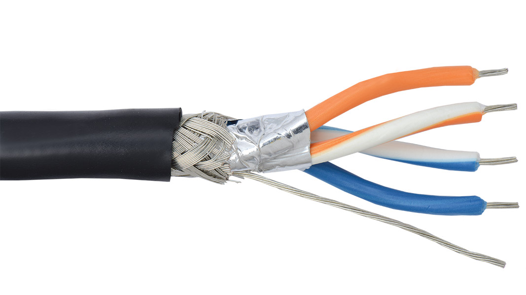
Lot of articles on the internet cover the electronic details of what DMX is which is of interest to those wishing to create products that send or receive and wish to comply to the standard. This is of no interest to lighting designers and electrical contractors. The architecture of a DMX control system is governed by the other side of the standard EIA485 this describes the electrical system that DMX uses as it’s bedrock. This is the roadway that the communication runs on; if this underlying infrastructure is not correct then the communications trying to use it will falter and the system will never be stable and reliable.
DMX Standard was originally adopted for use by “lampys” at touring events where large entertainment systems are setup up for a show or a series of shows before being all packed up into a number of trucks and moved to the next show.
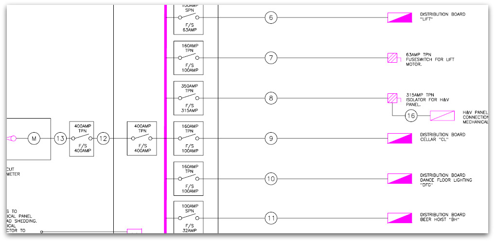
Power distribution for these shows is all done using flexible rubber cable and Ceeform cables connecting different parts of the systems using portable distribution units. The construction industry has a more cost effective and longer lasting method using steel wire armour and fixed distribution boards around a project.
The distribution for a project is designed in a drawing office by an electrical engineer.
The engineer designs the system by completing calculations and specifying suitable cabling and distribution panels to ensure that the system will work correctly and safely.
DMX is used by the construction industry primarily to control colour change lighting. By it’s nature a single colour change unit uses three or four channels of DMX and puts a unit load on the DMX controller of the system.
In the same way as the electrical distribution example above DMX requires design. It’s a simple thing to say but frequently the architecture of a DMX system is left to chance. When a ring main is required in a electrical system often the exact numbers of outlets and types of outlets will not be specified or indeed if a small change is required then the installing electrician will make the design change in a flash. This is simple as a the architecture (limits on length, number of outlets, spurs) is well known by that electrician through years of installing these simple systems.
DMX is a simple architecture however colour change systems can use a large number of DMX recievers and control channels. In addition to this systems should be designed to allow section testing by isolation and also to ensure downtime in certain areas of the system will not affect control over other parts of the system.
Simple DMX systems have a single cable connecting a number of fittings allowing a controller to control attributes on all these fittings independently. In reality all but the most basic DMX systems require boosters, splitters and termination to allow a stable system to exist and to ensure minimum installation time.
DMX is a not a proprietary control standard it is used by countless manufacturers and the size and complexity of DMX control required in a project is on the increase all the time.
So don’t chance it ! Were here to help!
More Reading:
The DMX 512-A Handbook


